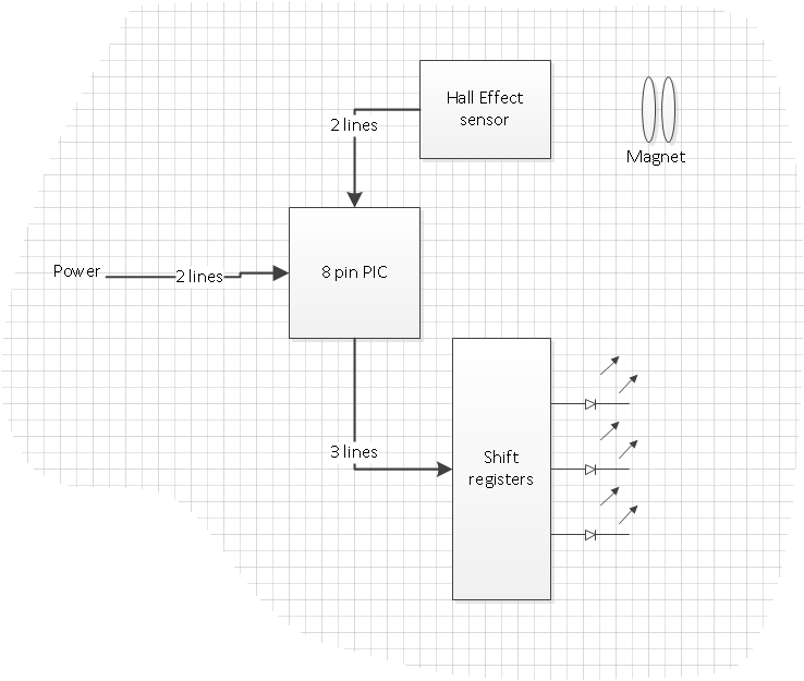
As per the plan (https://astrospanner.wordpress.com/2014/01/13/bike-spoke-images-the-plan), the PIC needs to drive a whole bunch of LEDs. The PIC I’m baselining (12F675) has 5 output pins (+two power + 1 input; 8 pin DIP package), and so driving more than 5 needs something extra. Some kind of multiplexing is clearly in order. For this, I’ve chosen to use a shift register. (An alternative is to use a binary to decimal converter; which expands 4 outputs to 10, but it doesn’t scale).
74×595
Mainly because I already know about it, I’ve chosen the 74HC595 shift register. It has 5 control lines, and 8 outputs. If you already know about it, feel free to skip this bit…
Because it’s an HC series, its relatively beefy, and so can supply enough current to drive an LED. The control lines are
- Data in
- Data Clock
- Parallel Load
- Output Enable
- Master Reset
The idea is that you “present” a logic high or low on the Data in, and then drive Data Clock high. Do this 8 times, and the internal registers contain the 8 values you presented on Data In. Send Parallel Load high, and the internal registers are loaded to the external registers, which are tied to the output pins. The output pins are then either high or low, based on the pattern you shifted in. And they stay there whilst you shift more stuff along…
Multiple ‘595s can be daisy chained together, all driven from the same Data Clock, same Parallel Load, so with, say 8 chips 64 leds can be addressed. Output Enable can be kept low, and Master Reset high, so they don’t have to be tied to the PIC. Lovely.
The circuit is as shown:

And when built (on a breadboard) it looks like this:

Boardboard 4, the reality
I’m using the Microchip MPLAB IDE for writing the code (it came with the PicKit1 programmer I’ve got) and I’ve installed the Microchip MPLAB XC8 Compiler so that I don’t have to bang my head against the wall in assembly code too much.
Installing XC8 was easy; download from https://www.microchip.com/pagehandler/en_us/devtools/mplabxc/
and install. When I started the new project in the MPLAB IDE, I just had to select the right toolsuite, which was already detected, and everything worked.
The code is split into four routines: first, init()
void init() {
 // disable interrupts
 INTCON = 0;
 // set internal oscillator freqeunecy
 OSCCAL = 0x80; // set internal oscillator to mid frequency
 // GP0,1,2 as outputs (=0) rest as inputs
 TRISIO = 0b00001000;

 // disable ADC
 ANSEL = 0b00000000; // set ANS[0:3] bits to zero
 GPIO = 0; // clear GPIO
}

And then two routines that either send a byte (ie 8 bits) to the 595, and another to "display" them.

void send_byte_to_595(char a) {
// Sends the byte a, LSB first, to the 74'595 shift register
 int i;
 char b;
b = a;
 for (i=0; i<8; i++) {
   if ((b & 0x01) == 0x01) {
      GPIO = GPIO | 0b00000010; // data is high...
     _delay(2);
   } else {
      GPIO = GPIO & 0b11111000; // data is low
     _delay(2);
   }
   GPIO = GPIO | 0b00000100; // clock high
   _delay(2);
   GPIO = GPIO & 0b11111000; // clear the bits
   b = b >> 1; // shift it right
  }
}
_delay(x) is a provided routine that adds x cycles of nops to the code. GPIO is a defined register that maps directly to the hardware outputs; each bit is an output. Nice and easy to use.
void display_595() {
// toggle the parallel load bit of the output to display the byte(s) that have been sent.
 _delay(2);
 GPIO = GPIO | 1;
 _delay(2);
 GPIO = GPIO & 0b11111110;
}
In this circuit they don’t need to be split, but it allows flexibility for different number of chips later (if need be).
The main() routine just then calls init() and then enters an infinite loop:
main() {
 char i;
 init();
 while ( 1==1 ) {
   for (i=0; i<255; i++) {
     send_byte_to_595(i);
     display_595();
     GPIO = GPIO ^ 0b00100000;
     _delay(1000000); // delay 1000000 cycles
   }
  }
}
Whilst I would love to claim this all worked first time, it didn’t. The debugging process added the additional LED onto pin 2, which worked sometimes, and didn’t work other times. This was most frustrating as it always worked whilst on the PICkit1 programmer board. I was poking around with a DVM checking wiring and then it would work for a couple of ticks, and then stop. After a while I actually read the datasheet and found the “master reset” function. I had it set to external, with pin 4, the master reset pin, floating. So it was reseting randomly. Change the config option to “internal”, and it worked happily.
Next step; synchronizing with the magnet sensor…
Addendum
One of the nice things about writing the code in C is that I now have two utility functions that I know work, and can be pulled into other projects, or at least other breadboards as required. But the XC8 compiler doesn’t do any optimization whilst in free mode. For the code I’ve written here, the memory summary is reported as
Memory Summary:
   Program space used 74h ( 116) of 400h words ( 11.3%)
   Data space used     Ch ( 12)  of 40h bytes ( 18.8%)
11% is OK at the minute, but the plan called for storing 128 * 3 bytes of just picture data, ie an additional 384 bytes of the 1024 words allowed. The overall memory usage may get bigger, and I’m not convinced that re-writing in assembly will be worth the trouble. Shifting to a bigger PIC will be though…